At Neptune™, we provide single-source, end-to-end solutions to help increase your operational performance and deliver the peace-of-mind reliability you expect for a range of markets and applications, including industrial water/wastewater, municipal
usage, agricultural applications and chemical metering and dispensing.
If you want to optimize your operation by automatically controlling the capacity of your Neptune 500 Series, 600 Series or 6000 Series Hydraulic Metering Pump, then include the Neptune Advanced Stroke Controller in your toolkit.
Once you have your Advanced Stroke Controller, the following comprehensive guide (part of our ProTips Series) will help you calibrate your Advanced Stroke
Controller to respond to a standard 4-20 mADC process signal.
Step 1
Connect the Advanced Stroke Controller to your Neptune Hydraulic Metering Pump. For detailed information on how to attach your Advanced Stroke Controller to your Neptune Chemical Metering Pump please see our blog post or our instructional video.
Step 2
Use a 6 mm wrench to unscrew the four screws and remove the front cover of the Advanced Stroke Controller. The calibration controller can be accessed by sliding the cover off.

Step 3
To set up the calibration controller, start by powering it up with a single phase 115/220 volt. First, connect the neutral wire (white) to the N (neutral) connector, and then connect the hot wire (black) to the L (live) connectors
on the backside. Next, connect the two input command connections from the analog 4-20 mADC process signal. Once the analog and power wires are connected, the controller display will show "POSITION."

Step 4
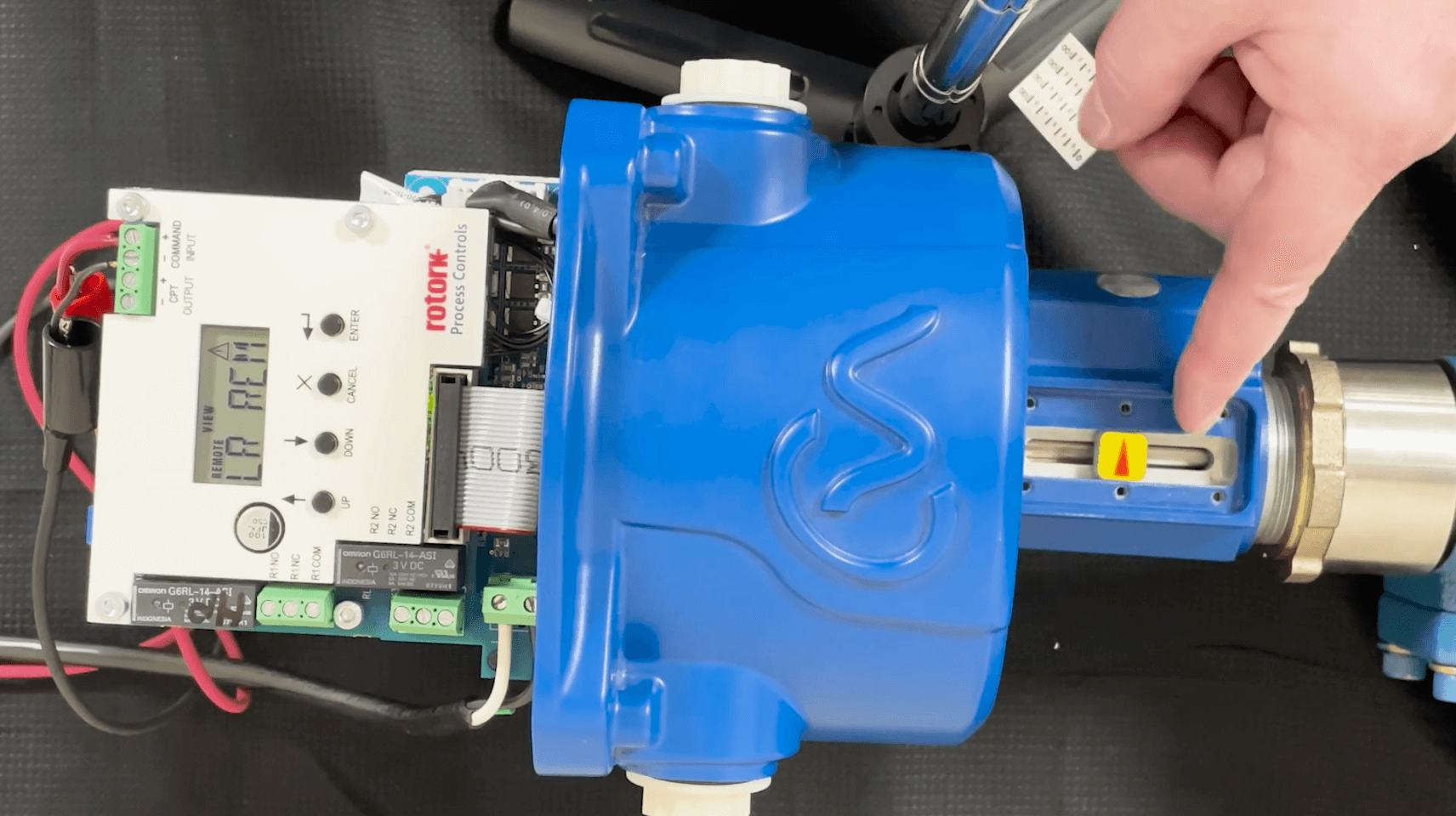
Use the scale (sticker) and place it on the desired zero point (which you can find through a calibration column or a water meter). Adjust the 4-20 mADC process signal accordingly and set the zero point on the controller
(Step 5).
Step 5
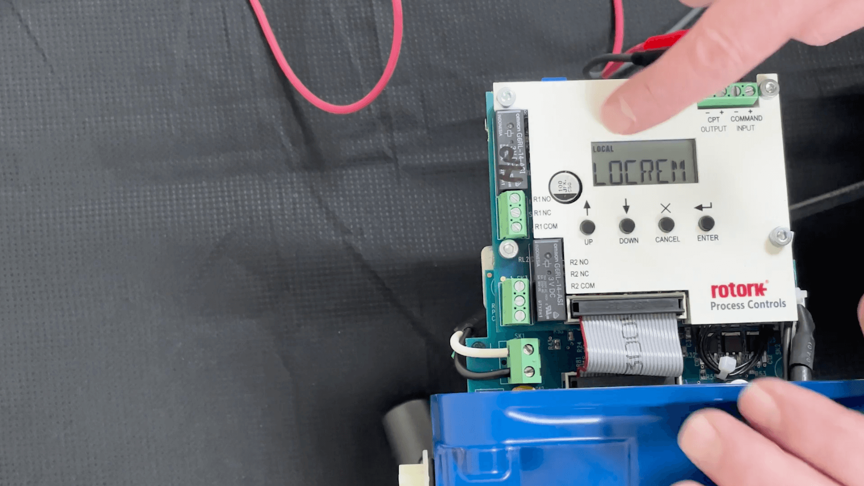
You must set your controller to Local Remote when adjusting to a certain point. To do so, use the Up or Down arrow until you find Local Remote. Then, press Enter. Press Enter again until the small text above Local Remote
reads Edit. Then, use the Up or Down arrows until you find Local. Then, hit Enter to save the setting.
Step 6
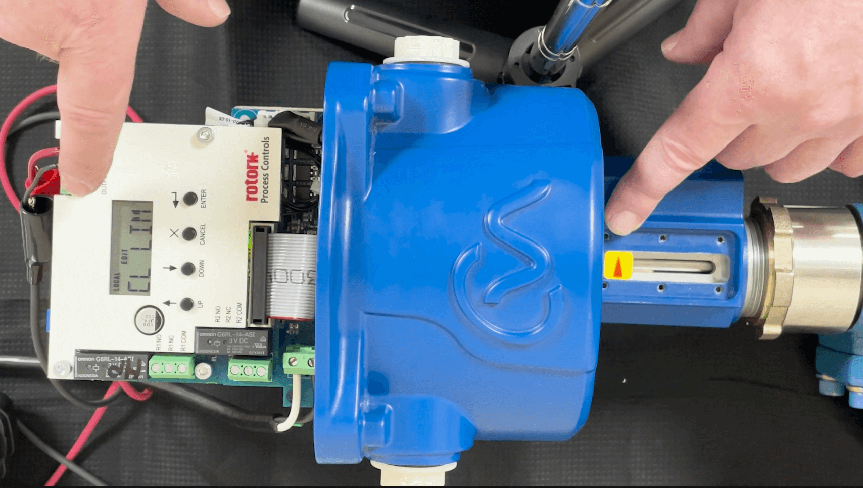
Once the zero point is set, set the zero limit. Use the Up or Down arrows on the controller until you find CL Limit, and then hit Enter. Hit Enter again until the small text above CL Limit reads Edit. Adjust the 4-20 mADC
process signal accordingly and then hit Enter on the controller to save the setting. Now, adjust the zero limit using the Down arrow on the controller until you reach 100% of the scale. Once there, hit Enter again to save the setting.
Step 7
Check your 4-20 mADC process signal and the 0 and 100% span by setting the controller back into Local Remote (refer to Step 5). Use the scale sticker to check the span of the stroke. Once verified, the Advanced Stroke
Controller is successfully calibrated.